Grand Coulee Dam Photo Gallery

(Construction Page)
This page contains various pictures taken during the dam's construction. All photos are stored in JPEG format to provide good color and image quality in a minimum amount of space. Photos are 1024 pixels in length measured on the long axis and take up approximately 100kB of storage.
All photos are provided courtesy of the U.S. Bureau of Reclamation unless otherwise noted. Special thanks to Judy Quill at the Bureau for allowing me access to the photo archives and for duplicating selected prints.
 117kB JPEG (1024 x 790)
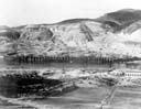
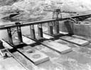
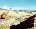
West Cofferdam
This is a close-up of the 5000 foot long west cofferdam taken March 20, 1935. The purpose of the cofferdam is to divert water away from the excavation area so that the ground can be prepared down to and below the level of the river.
 120kB JPEG (1024 x 790)
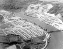
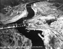
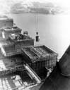
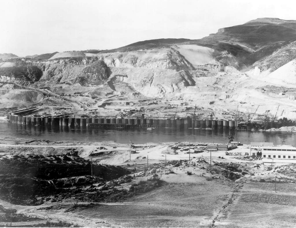
Aerial Overview
This is an aerial view of the dam site taken on May 05, 1935. As can be seen a major amount of earth removal had already occured on the west (right) bank at the time of this photo. An extensive cofferdam is visible on the west bank near the center of the picture.
 116kB JPEG (1024 x 790)
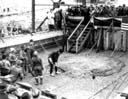
First Concrete
Governor Clarence Martin using an air vibrator to settle the "first" concrete pour at Grand Coulee Dam. Photo taken December 12, 1935.
 149kB JPEG (1024 x 790)
West Side Dam Base Flooding
This is a photo taken of the construction area behind the west cofferdam. Sections "H" and "I" of the cofferdam have been removed to allow water to flow into the west side diversion channels. Eventually the west cofferdam was removed entirely and the completion of the east cofferdam forced the entire flow of the Columbia through the diversion channels. This allowed work to proceed on the rest of the dam without interrupting the flow of the river. The Contractor's Camp (Mason City) can be seen in the background. Photo taken November 20, 1936.
 144kB JPEG (1024 x 790)
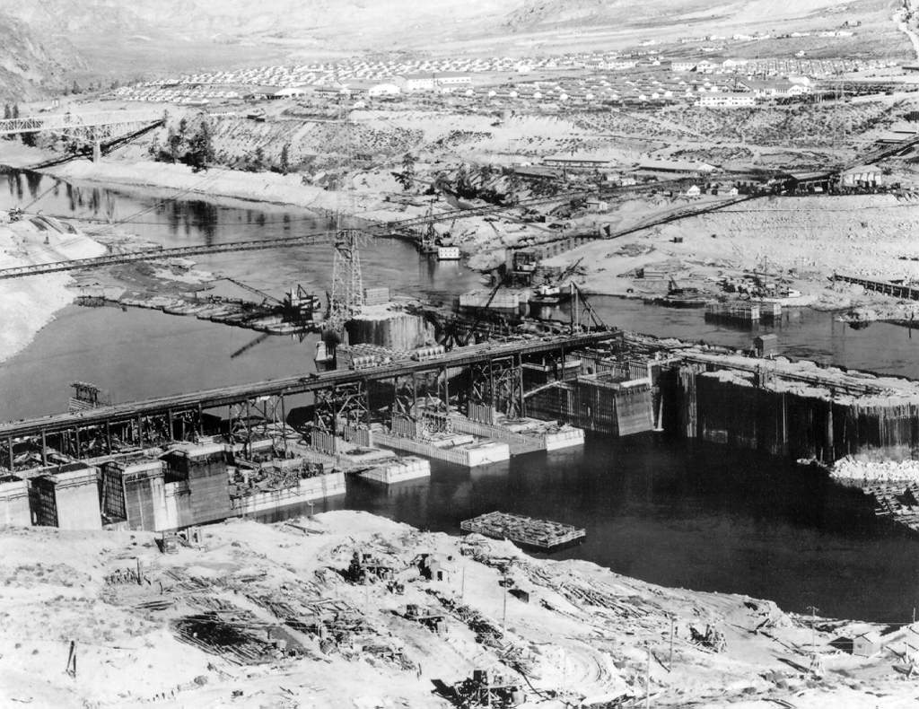
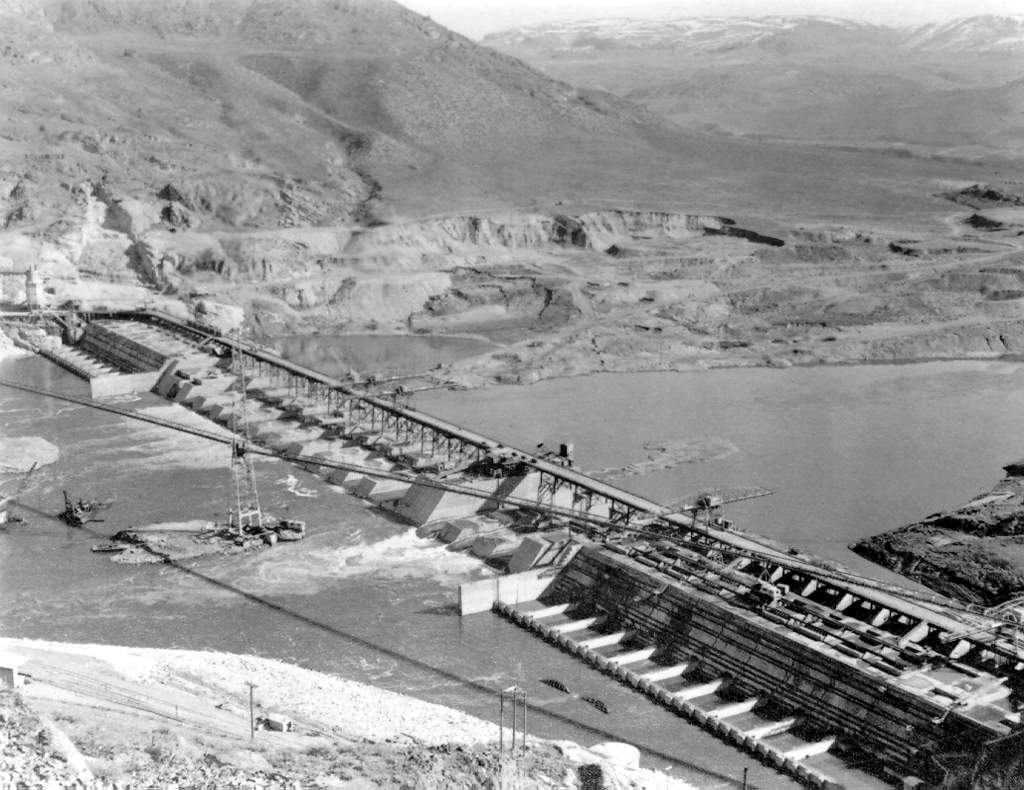
Aerial Overview of West Dam Construction
This photo was taken from the upstream side of the dam on March 16, 1937. Note that the west (left) cofferdam has been removed and water is being diverted through channels in the west dam base by an extensive cofferdam on the east side of the river. This technique of protecting only half of the construction site
at a time allowed the base of the dam to be built without interrupting the flow of the river.
 132kB JPEG (1024 x 790)
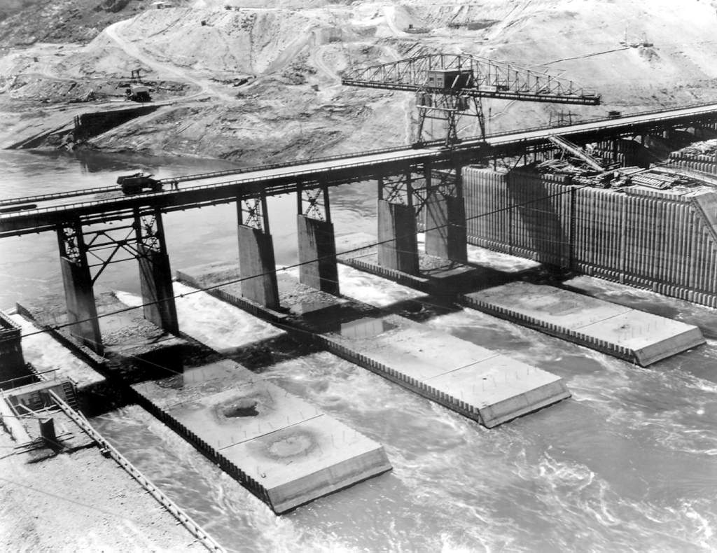
Close-Up of West Side Diversion Channel
This is a close-up view of the west side diversion channels used to accommodate the flow of the river while work proceeded on the east side of the dam (see photo above). Photo was taken on April 29, 1937.
 126kB JPEG (790 x 1024)
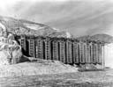
Construction of Outlet Tube Trashrack Assembly
Here workmen are seen placing the steel grates (or trashracks) into the trashrack assembly of one of the dam's sets of spillway outlet tubes. Photo taken on November 30, 1937.
 113kB JPEG (1024 x 790)
Dam Base Completed
In this picture both the east and west cofferdams have been removed and the two sides of the dam are joined together. This shot was taken shortly after the completion of the dam base construction phase which marked the end of the MWAK Co. construction contract. (Two prime contractors were used to build the dam. MWAK was responsible for constructing the dam's base while Consolidated Builders Incorporated finished the project). The construction trestles at elevation 1024 (feet above sea-level) top concrete which had been poured to a maximum elevation of 1010 in the abutment sections and to 945 in the spillway section with the exception of blocks 39 and 40 which were carried to elevation 1000. The powerhouse foundations were completed to elevation 948.8 and the training walls to elevation 980. Photograph taken on March 8, 1938.
 94kB JPEG (790 x 1024)
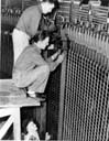
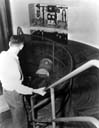
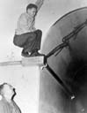
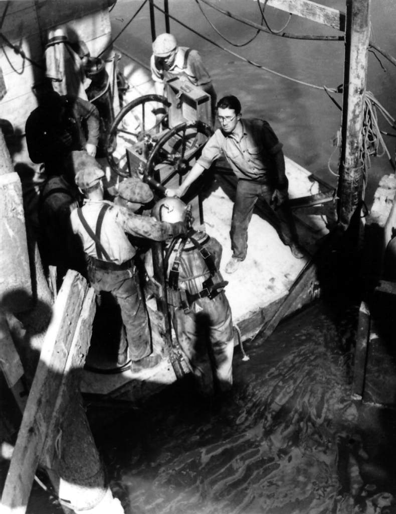
Hand Driven Air Pump
Here workmen are seen operating a hand driven air pump which provides breathing air to divers as they inspect submerged areas of the dam. There was no date associated with the photograph.
 116kB JPEG (790 x 1024)
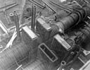
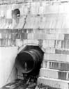
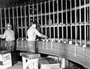
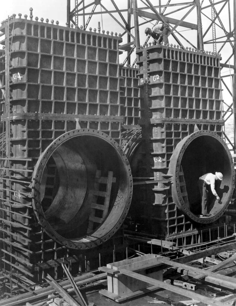
Outlet Tube Gate Valve Close-Up
This is a close-up of two of the upstream/downstream sets of gate valves which control flow through the dam's 60 outlet tubes. The outlet tubes are 102 inches in diameter. Photo taken on May 02, 1939.
 103kB JPEG (790 x 1024)
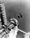
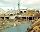
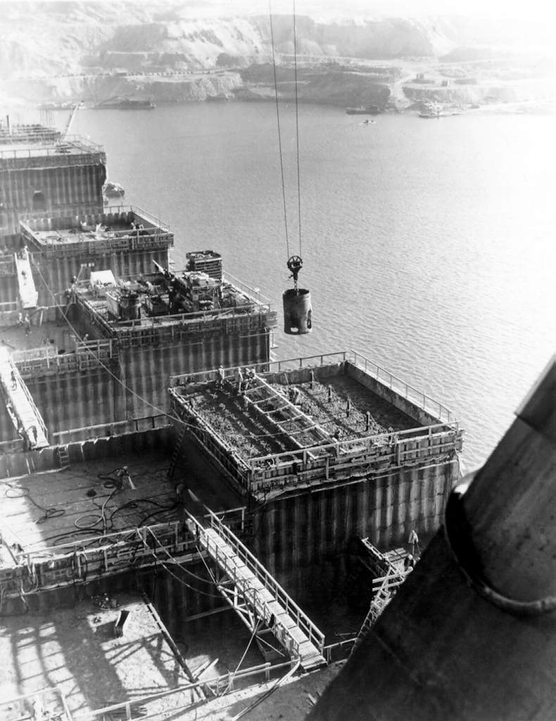
Spillway Construction
This photo shows one of the large cement buckets transporting a load of concrete to the spillway area of the dam. Notice that the dam was constructed as a series of blocks each of which was about 50 feet square and five feet tall. The block numbers are still used at the dam as reference points. For instance, the right powerhouse tour elevator is located at block 84. Pipes embedded in the new concrete carried cooling water from the river to remove heat generated by the cement as it cured. These pipes were subsequently filled with grout. Photo taken on November 14, 1939.
 134kB JPEG (1024 x 790)
Outlet Tube Gate Valves
Here is another photograph of a set of outlet tube gate valve assemblies. Note the welder to the right of the upper set of valves. Photo taken on January 02, 1940.
 89kB JPEG (790 x 1024)
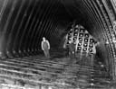
Generator Penstock
Shown is a workman standing in one of the dam's original 18 foot diameter generator penstocks. The penstocks carry water from the upstream side of the dam into generator's turbine area. Photograph was taken January 10, 1940.
 138kB JPEG (1024 x 790)
Pumping Plant Trashracks
This is a picture of the back side of the pumping plant foundation. Each pump inlet tube is shielded by a vertical column covered by steel grates. These grates, known as trashracks, protect the pumps from sucking up debris from the river. Photo taken on October 23, 1940.
 106kB JPEG (790 x 1024)
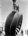
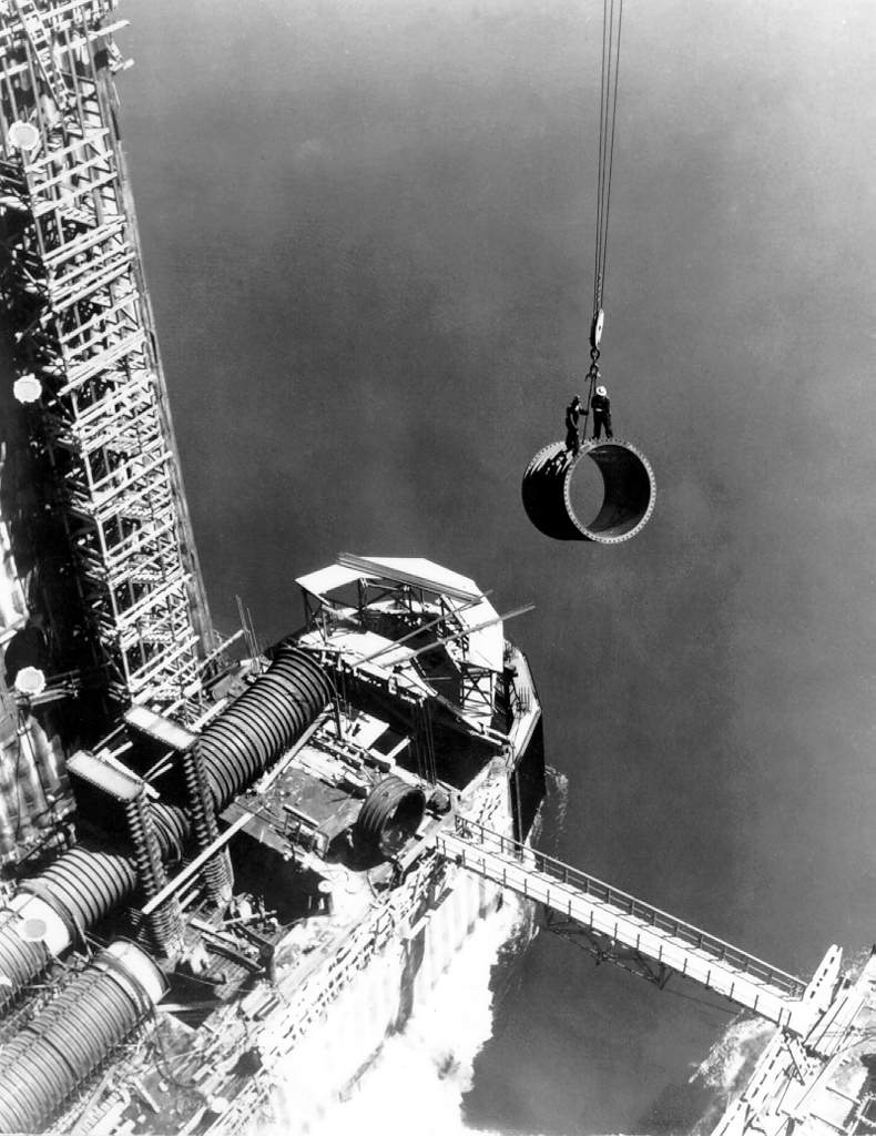
Outlet Tube Assembly
Two workmen catching a ride on a section of outlet tube being installed in the spillway section of the dam. The dam contains 60 outlet tubes in all which are laid out in three rows of twenty tubes each. The 102 inch diameter tubes were initially used as a means to divert the river as dam construction proceeded. They now serve as a supplementary method of controlling the level of Lake Roosevelt behind the dam. As can be seen, the outlet tubes are placed in pairs. In this photo the upstream- and downstream gate valve assemblies are installed and can clearly be seen on the left most tube. Sometime after dam construction was complete the bottom 20 tubes were filled with concrete. Photo taken in 1941.
 109kB JPEG (1024 x 790)
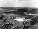
Aerial View
This is an aerial photograph of the partially completed dam taken on June 15, 1941. The normal Columbia river flow is allowed to pass through a series of 102 inch diameter outlet tubes which pass through the dam's spillway. There are 60 such tubes in all. They are laid out in three rows with each row containing two sets of five pairs each. The outlets of the lowest row of tubes are below the water level on the downstream side. Note that the tubes are not symmetrical on the spillway but appear mostly on the east (left) side. Other significant features include the large depression above and to the right of the dam. This became Cresent Bay as the lake behind the dam filled. The steel highway bridge in the foreground serves as the primary means of travel between the east and west sides of the city of Coulee Dam.
 139kB JPEG (1024 x 790)
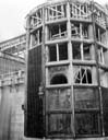
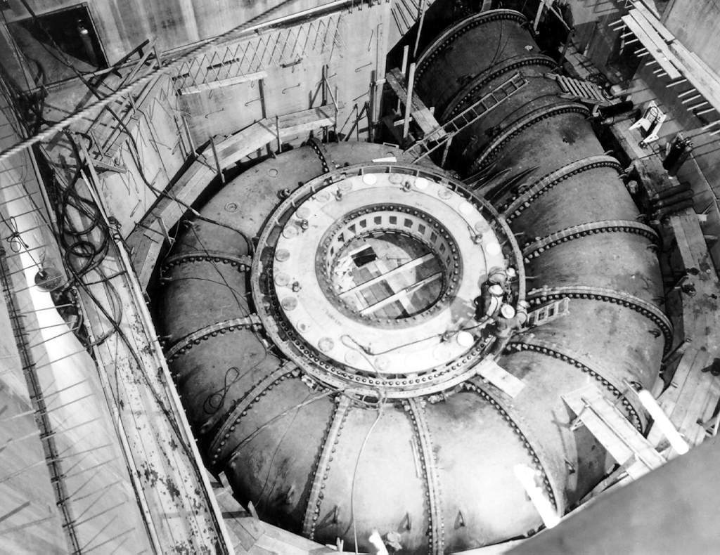
Generator Scrollcase
This is the scrollcase for generator L-1 (now called G-1) in the left powerhouse. The central depression in the snail-shaped scrollcase is the turbine pit. Water flows into the turbine from all sides through the rectangular slots clearly visible in the sides of the pit. The diameter of the pipe forming the scroll case steadily decreases from 18 feet at the penstock outlet on the right. This provides an equal flow of water into all sides of the turbine. The L-1 generator went on-line on April 07, 1942. Photo taken on September 11, 1941.
 81kB JPEG (1024 x 790)
Left Powerhouse Generator Turbine
Here a workman is inspecting one of the generator turbines just before its installation in the left powerhouse. Photo taken on December 18, 1942.
 90kB JPEG (790 x 1024)
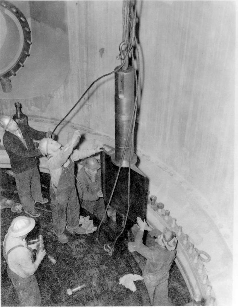
L-4 Wicket Gate Installation
Here men working in the left powerhouse install one of the wicket gates in the L-4 (now called G-4) turbine pit. This and other wicket gates form a ring of louvers around the turbine which can be opened and closed like venetian blinds to control the flow of water. As the electrical demands on a generator increase more water is required to keep it spinning at the same rate. Once a generator is up to speed and on-line minute changes in the position of the wicket gates are used to keep the the generator spinning at exactly 120 rpm (the exact rotation rate is a function of the generator circuit design. On the left- and right powerhouse generators 120 rpm results in 60Hz AC power). This photo was taken on November 15, 1943.
 155kB JPEG (1024 x 790)
Interior of Spillway Drum Gate #11
This picture shows two workmen standing inside one of the dam's large spillway drum gates. As can be seen the gates are huge and hollow. The 135 foot long, 28 foot tall gates float and they are raised and lowered by controlling the level of water in chambers underneath them. Photo taken on January 05, 1944.
 122kB JPEG (1024 x 790)
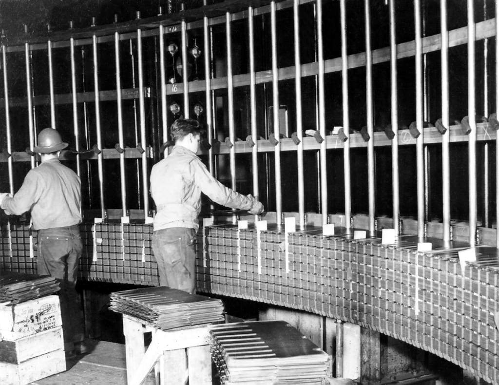
L-9 Stator Construction
Here workmen can be seen placing the thin sheets of iron which form the L-9 (now called G-9) generator's stator core. Each iron sheet is insulated from the ones above and below it by a thin layer of lacquer. This prevents the changing magnetic fields inside the operating generator from producing eddy currents in the steel which would rob the generator of power and create undue heating. Note the slots in the steel plates. The copper coils which form the generator's stator winding fit between these slots (see photo below). There is no date associated with this photograph but the L-9 generator first went on-line on April 23, 1948 so I'd assume this picture was taken some time in '47 .
 146kB JPEG (790 x 1024)
L-9 Stator Construction
Here workmen can be seen placing the copper stator windings into the slots of the laminated steel stator core on the L-9 (now called G-9) generator. As each segment of the winding is placed into its slot it is connected to the other segments at top and bottom to form a continuous circuit. The winding segments are insulated from the steel core by a fiber/resin insulation. Again there is no date associated with this picture but I assume it was taken some time in late '47 or early '48.
 55kB JPEG (790 x 1024)
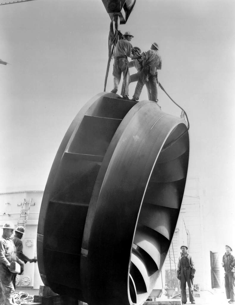
Generator Turbine Impeller
Ending a 5,000 mile roundabout trip from Newport, VA., this 150,000 rated horsepower turbine impeller is shown here being unloaded at the dam site. The unit was built by the Newport News Shipbuilding and Drydock Co. It couldn't be shipped directly to the dam because it would not clear railroad tunnels on the shortest route. At the time of installation this and the other turbines at Grand Coulee were the biggest in the world. Photo taken on June 25, 1947.
 94kB JPEG (1024 x 825)
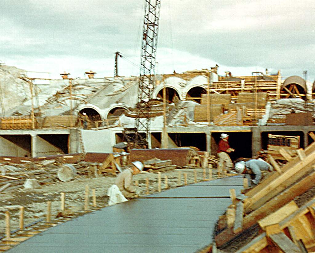
Feeder Canal Construction
This photo shows the construction of the feeder canal which carries water from the dam to Banks Lake 1.8 miles to the west. There was no date associated with the photo.
 126kB JPEG (1024 x 825)
Feeder Canal Construction
This photo shows construction on the feeder canal headworks. This is where water first enters the feeder canal. The tubes in the center of the picture are the outlets from the pumping plant below. No date was associated with the picture.
 78kB JPEG (1024 x 790)
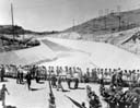
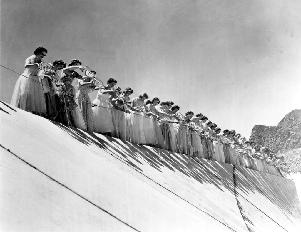
Water-of-all-States Ceremony
Fifty princesses and the queen of the Washington State Apple Blossom Festival participated in a symbolic pouring ceremony as they emptied gallon jugs of water from all the states, the territories of Alaska and Hawaii and the District of Columbia into the newly completed feeder canal. This ceremony was to symbolize the contribution of all the nation to the project and in turn, the benefit the project would mean to the national wealth when irrigation started the following spring. Photo taken on June 14, 1951.
 91kB JPEG (1024 x 790)
Irrigation Reservoir Begins to Fill
Water pours from the headworks of the feeder canal located 280 feet above the surface of Lake Roosevelt and the pumping plant. In the foreground are the princesses of the Washington State Apple Blossom Festival which participated in the symbolic pouring of water into the canal during the dedication ceremonies. Photo taken on June 14, 1951.
 68kB JPEG (790 x 1024)
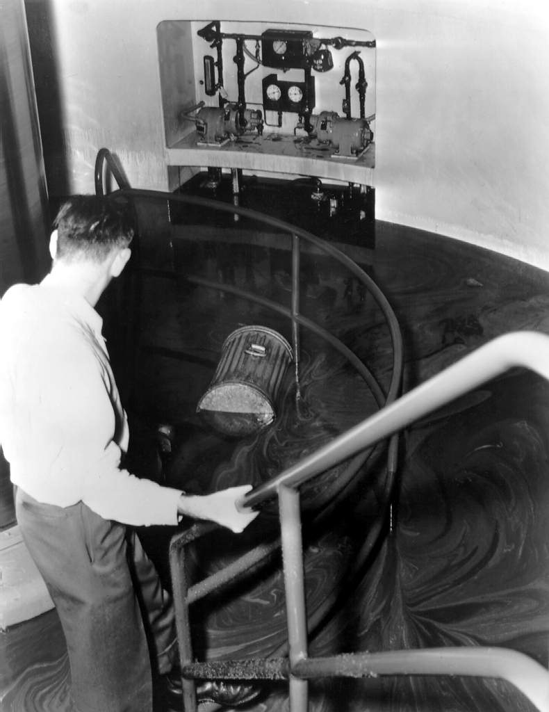
Flooded Turbine Pit
On March 14, 1952 at about 10:30 a.m., some of the galleries within the dam were partially flooded when an operator accidentally opened an outlet tube gate valve on the 1050 level of Block 55. The outlet tubes, which run though the east side of the spillway, are used as an auxillary means to regulate the level of the reservoir behind the dam. The operator was following a procedure to drain a number of the outlet tubes in preperation for sandblasting and painting. He mistakenly believed that he was closing a valve which was already open. In fact, that particular outlet tube was being used for paint durability tests and as such its upstream gate valve was already closed. When the operator activated the gate machinery he was unknowingly opening, not closing, the valve. The outlet tube is normally isolated from the service gallery by a bolted cover. Although the 200 pound access cover was in place the men doing the previous paint testing had not resecured it. As the upstream valve opened it allowed water to rush into the outlet tube. Blocked by the closed downstream valve the mounting pressure blew the access cover into the gallery and a jet of water began to stream east and west through the gallery (see the two photos below). Water entered the powerhouses at the 950 level and flooded a number of the turbine pits. Much of the lubrication oil for the turbine guide bearings was displaced by the heavier water and certain generators needed to be shut down to avoid bearing damage. This photograph was taken in the pit of turbine L-8 (now called G-8). The galvanized can floating in the water and oil mixture was swept into the pit from the 951 floor. Such cans were used in disposing of oily wiping rags. Oil circulation pumps are shown in the background. Maximum depth of the oil and water is shown by the oil on the stair rail in the right foreground. Photo was taken on March 14, 1952.
 59kB JPEG (790 x 1024)
Damage From Outlet Tube Accident
This photo, taken the day after the March 14, 1952 outlet tube flood, shows a piece of the ladder that had been bolted to the shaft which led down into the outlet tube. The ladder was torn to shreds as the force of the inrushing water shot the 200 pound access cover through the shaft. Shown in the picture are Milton Berg (above) and Norman Holmdahl (standing). Both men were later awarded gold medals by the Department of the Interior for their part in eventually shutting off the water and saving the dam. Six other gold medals and one silver medal were also awarded. Photo taken on March 15, 1952.
 80kB JPEG (790 x 1024)
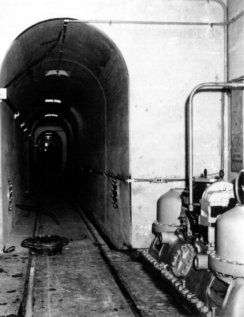
Block 55 Outlet Tube Accident Site
This photo was taken at block 55 along the 1050 gallery three days after the accident described above. The access cover can be seen lying on the floor. The gate valve control machinery is visible against the right wall. Photo taken on March 17, 1952.
This page is maintained by Charles Hubbard as a private effort. Mr. Hubbard is in no way associated with the U.S. Bureau of Reclamation or the Columbia Basin Project.
| Created: |
April 20, 1996 |
| Modified: |
April 21, 1996 |
 117kB JPEG (1024 x 790)
 120kB JPEG (1024 x 790)
 116kB JPEG (1024 x 790)
 149kB JPEG (1024 x 790)
 144kB JPEG (1024 x 790)
 132kB JPEG (1024 x 790)
 126kB JPEG (790 x 1024)
 113kB JPEG (1024 x 790)
 94kB JPEG (790 x 1024)
 116kB JPEG (790 x 1024)
 103kB JPEG (790 x 1024)
 134kB JPEG (1024 x 790)
 89kB JPEG (790 x 1024)
 138kB JPEG (1024 x 790)
 106kB JPEG (790 x 1024)
 109kB JPEG (1024 x 790)
 139kB JPEG (1024 x 790)
 81kB JPEG (1024 x 790)
 90kB JPEG (790 x 1024)
 155kB JPEG (1024 x 790)
 122kB JPEG (1024 x 790)
 146kB JPEG (790 x 1024)
 55kB JPEG (790 x 1024)
 94kB JPEG (1024 x 825)
 126kB JPEG (1024 x 825)
 78kB JPEG (1024 x 790)
 91kB JPEG (1024 x 790)
 68kB JPEG (790 x 1024)
 59kB JPEG (790 x 1024)
 80kB JPEG (790 x 1024)